A “Green” Environmentally friendly Inert Gas Solution to fulfill Fire Suppression requirements in today’s Data Center Facilities.
In our new VOLICO 2.0 Broward Data Center, we are utilizing the Inergen Fire Suppression System manufactured by Ansul. This is an engineered fire suppression system utilizing a fixed nozzle gas distribution network. This system is also designed in compliance with the National Fire Protection Association (NFPA) draft Standards, “Clean Gas Fire Extinguishing Systems”.
The Inergen Gas or the “Active” Ingredients in the Inergen Fire Suppression System is a mixture of three (3) inerting or oxygen diluting gases consisting of: 52% Nitrogen, 40% Argon and 8% Carbon Dioxide. In laymen’s’ terms, Inergen Gas extinguishes fire by lowering the Oxygen content below the level that supports combustion. When the Inergen gas is discharged into a room, it releases the proper mixture of gases that reduces the amount of Oxygen in the air from 21% down to below 15%, yet still allows a person to breathe in this reduced Oxygen atmosphere. In fact, due to the release of this Inergen gas, the Carbon Dioxide in the room is increased from less than 1%, a normal level for this gas, to approximately 4%. This in turn increases a person’s respiration rate and also the human body’s ability to absorb Oxygen into the bloodstream in the lungs. Simply stated, the human body is naturally stimulated by the increase in Carbon Dioxide in the room. Similar to Asthma inhalers, this biochemical pathway allows for deep and rapid breaths to compensate for the lower Oxygen content in the room’s atmosphere.
As the Inergen gas consists of inert gases present in the Earth’s atmosphere, it is truly a “Green” Gas which does not deplete the Earth’s Ozone Layer, nor does it contribute to Global Warming, and most importantly does not further pollute our atmosphere with any toxic chemicals found in other suppression systems such as FM200, FE25 Ecaro, and Halon “Agent Based” suppression systems.
Deployment of the Inergen Fire Suppression System in the Data Center
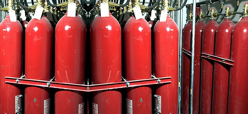
The basic Inergen system consists of extinguishing Inergen gas stored in high strength alloy steel cylinders located in a safe and accessible location. Various types of actuators or distribution deployment “vehicles” either manual or automatic, are available for release of the gas into the area affected by fire. The gas is distributed and discharged into the affected area through a network of piping and nozzles. Each nozzle is drilled with a specific fixed opening designed to deliver a uniform amount of discharge to the protected area. For larger hazards, where three (3) or more cylinders are required, a screwed or welded pipe manifold assembly is deployed. The cylinders are connected to the distribution piping or the manifold by means of a flexible discharge bend and check valve assembly.
An ANSUL Autopulse IQ 318 Control Unit provides the power to set off the alarm and trouble signals in addition to actuating the automatic extinguishing system. This Control Unit constantly monitors the release circuit, detector circuits, alarm relays and stand-by batteries.
Emergency power (DC) for the System will be provided by a gel cell battery and charger assembly housed in the Control Unit. In the event of line power failure, the System is automatically switched to battery power and will operate for approximately 24 hours.
ANSUL photoelectric and ionization detectors will provide automatic detection. The gas discharge will be governed by two (2) separate detection zones that are in the alarm system, located in the protected area, prior to the gas release start-up sequence.
The initiation of any single detector will cause only an audible alarm and visual indication on the ANSUL Control Unit. The initiation of a second detector in an opposite zone will activate the release sequence and gas will be released at the end of a specified time delay period.
The System will also be capable of immediate gas discharge through the operation of a manual pull station located at the exit. This pull station is the dual action type requiring two (2) distinctive functions to operate.
Lastly, but most importantly, a constant manual pressure type abort switch will be provided to detain a System discharge in the event of an unwanted occurrence, or one triggered in error.